Model Aurona Wash IP65Edition EN · 04 / 2026 · V1Dokument-Nr. AUBLFW-EN-01
IP65 LED Wash · RGBWS 5-in-1 · 6 Pixel Segments
Aurona Wash
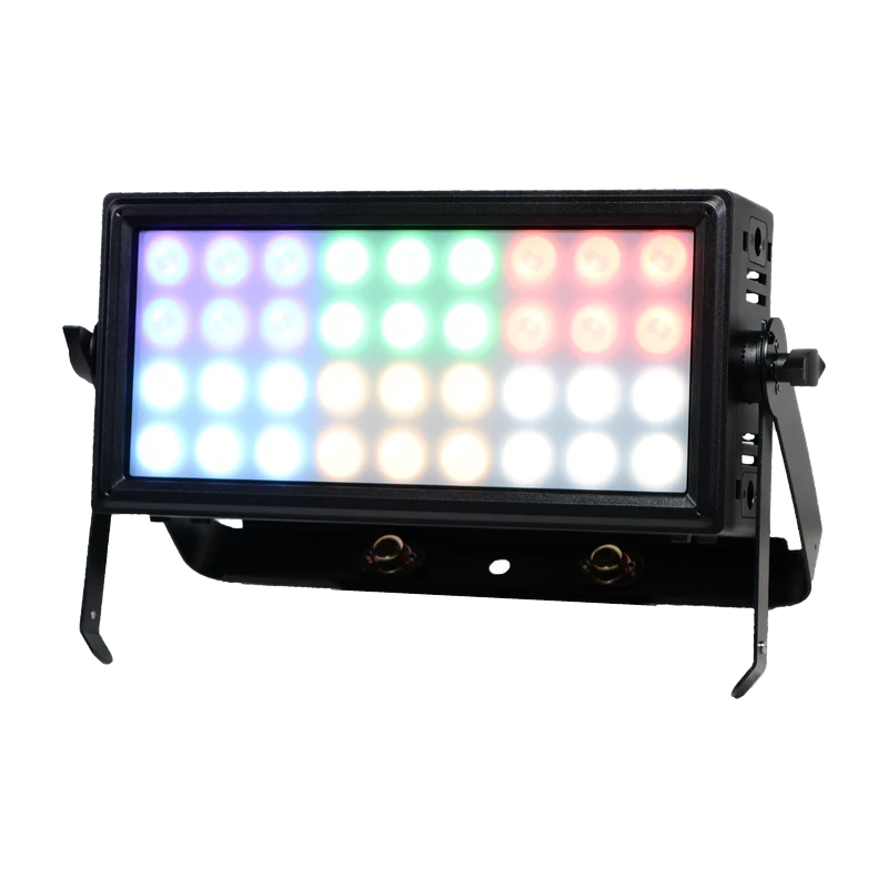
Weatherproof wash with 36 × 10 W RGBWS LEDs (white 6000 K, warm white 2500 K), CRI 95+, electronic frost, six individually controllable segments and ten DMX channel modes
Operating manual. Please read in full before first use and keep for future reference.
Light source
36 × 10 WRGBWS 5-in-1
Lens
20°12° / 40° optional
DMX channels
1–3310 channel modes
IP rating
IP65Outdoor
Aurona Wash IP65Foreword · About this document
Foreword
00Welcome
Thank you for choosing the Aurona Aurona Wash IP65 — a weatherproof wash with 36 RGBWS LEDs, electronically adjustable frost filter and six individually controllable pixel segments.
This document covers installation, operation, menu navigation and the complete DMX mapping of all channel modes. Read the manual in full — especially the Safety Information chapter — before first use, and keep it with the unit.
0.1Intended Use
The fixture is weatherproof (IP65) and intended for professional use only. Maximum ambient temperature: 40 °C. The housing may be hot during and after operation.
Warning — Risk of Electric ShockDo not open this device, there are no user-serviceable parts inside. Do not look at the light source when the device is on. ONLY connect this device to a grounded and protected circuit, and never to a dimmer or rheostat.
Caution: the housing of this unit may be hot during and after operation.
Install this device in a location with adequate ventilation, at least 50 cm (20 in.) from adjacent surfaces.
Do not leave any flammable material within 50 cm of this unit while operating or connected to power.
The mounting point must hold at least 10× the weight of the fixture; secure it additionally with a suitable safety cable of adequate load rating, in accordance with local guidelines and statutory requirements.
Do not operate this device if the housing, lenses or cables appear damaged.
ONLY use the hanging bracket to carry this device.
In case of a serious operating problem, stop using the device immediately.
The maximum ambient temperature is 40 °C (104 °F). Do not operate this device at higher temperatures.
1.1Power Input & Power Linking
This device has an auto-switching power supply for 100–240 V AC, 50/60 Hz, with True1 input and output. When power-linking fixtures, do not exceed the permissible total current of the circuit.
Aurona Wash IP6502 · Technical Specifications
Chapter 02
02Technical Specifications
Light Source & Photometrics
Light source
36 × 10 W RGBWS-LED (S = warm white) · W 6000 K · S 2500 K
This device can be mounted in many orientations provided each individual device is secured by the correct mounting bracket. The double yokes allow both free-standing floor use and horizontal hanging; mounting points on the top and bottom are provided for vertical rigging. Cam locks accept ¼-turn omega brackets; for linking multiple fixtures, 6 coffin locks and 3 tool-free lock handles are provided.
Safety CableThe mounting point must hold at least 10× the weight of the fixture; secure it additionally with a suitable safety cable of adequate load rating, in accordance with local guidelines and statutory requirements.
3.2Fuse Replacement
If the fine-wire fuse fuses, only replace it by a fuse of the same type and rating. Before replacing the fuse, unplug the mains lead.
Unscrew the fuse holder on the rear panel with a fitting screwdriver (anticlockwise).
Remove the old fuse from the fuse holder.
Install the new fuse in the fuse holder.
Replace the fuse holder in the housing and fix it.
Select static colour; W = cool white, S = warm white — see chapter 4.1
Dim <000> – <255>
Intensity of each static colour
ManualC
R / G / B / W / S <000> – <255> · Dim <000> – <255> · Sb <000> – <100>
Set intensity of each colour separately for colour mixing, and the strobe rate
Manual W
WT<001> – <011> · <Dim000> – <Dim255>
Set the colour temperature WCT 01–11 and adjust brightness
Auto Pr
Pr01 – Pr17 · Sp<000> – <100> · Dim<000> – <255>
Built-in automatic program, run speed and dimmer level
Fr<000> – <100>
Transparency level of the electronic frost
Sound
Sen<000> – <100>
Sound active mode and sensitivity level
Mas/Sla
<M> <S>
Select master/slave mode
Frost
Frost<000> – <100>
Transparency level of the electronic frost
Wireless
<ON> / <OFF>
Turn wireless DMX on or off
<EL Mode> → CH<00>–<05>
Select EL mode and group number
<W-DMX_R> → <Receive> / <Delete>
Set the fixture to receive wireless DMX
<W-DMX_T> → <Transim> / <Create>
Set the fixture to transmit wireless DMX
Fan Set
<off> <Auto> <Low> <Med> <Hig>
Turn the fan off or on, select speed
Temp
Temp <xxx °C>
Current temperature of the driver PCB
Update
<N> / <Y> · <START>
Update firmware or update another fixture
Reset
<N> <Y>
Recover factory default
Aurona Wash IP6504.1 · Static Colours
4.1Static Colours — 30 Combinations
In StaticC mode, use "Up" and "Down" to select the desired solid colour and press "Enter" to save. The codes are composed of the five LED colours: R red, G green, B blue, W cool white, S warm white. The intensity is then set via Dim from 000 to 255.
Value
Colour combination
R
Red
G
Green
B
Blue
W
White
S
Warm white
GB
Green + Blue
RG
Red + Green
RB
Red + Blue
RW
Red + White
GW
Green + White
BW
Blue + White
WS
White + Warm white
RS
Red + Warm white
GS
Green + Warm white
BS
Blue + Warm white
Value
Colour combination
RGB
Red + Green + Blue
RGW
Red + Green + White
RBW
Red + Blue + White
GBW
Green + Blue + White
GBS
Green + Blue + Warm white
BWS
Blue + White + Warm white
RGS
Red + Green + Warm white
GWS
Green + White + Warm white
RWS
Red + White + Warm white
RGBS
Red + Green + Blue + Warm white
GBWS
Green + Blue + White + Warm white
RGBW
Red + Green + Blue + White
RBWS
Red + Blue + White + Warm white
RGWS
Red + Green + White + Warm white
RGBWS
Red + Green + Blue + White + Warm white
Aurona Wash IP6504.2 · Manual, Auto & Sound Operation
4.2Manual Colour Mode (ManualC)
In Manual C mode, use "Up" and "Down" to set the intensity of each colour (R, G, B, W, S) from 000 to 255 and select the strobe speed from S000 to S100 (S000 is strobe off). Press "Enter" to save.
4.2.1Colour Temperature (Manual WCT)
Select the colour temperature from <WT01> to <WT11>, then use "Up" or "Down" to select the intensity between 1 and 100 and press "Enter" to confirm. The same eleven colour temperatures are available in the 12-channel mode on channel 8 (values 201–255) and in the 14-channel mode on channel 13.
4.2.2Auto Programs (Auto Pr)
Seventeen built-in automatic programs (Pr 01 – Pr 17) are available. In Auto Pro mode use "Up" and "Down" to select the program, confirm with "Enter", then set the run speed from <Sp000> to <Sp100>, the dimmer from <dim000> to <dim255> and the frost transparency from Fr<000> to Fr<100>. Press "Enter" to save. The programs correspond to auto effects 1 to 17 on channel 9 of the 12-channel mode.
4.2.3Sound Active Mode
In Sound mode use "Up" and "Down" to select the sensitivity from Sen000 to Sen100 and press "Enter" to save.
4.2.4Master / Slave
Set the master fixture to one of the stand-alone operating modes: automatic, sound, static colour or manual colour. On the slaves, enter Mas/Sla mode, set it to "S" and press "Enter" to confirm.
4.2.5DMX Loss & User DMX
By standard the fixture holds the last signal when no DMX signal is present or the signal is lost. Via DMX Loss you can instead select Hold, Blackout, Manual (last manual colour) or Auto (last auto show selected). Under User DMX you can assign a function per channel; set the channel following the last used one to End. To select this mode, choose User under DMX channel mode.
Each fixture is equipped with a built-in WDMX module and an antenna, allowing it to both receive and transmit DMX signals without any DMX cables. To enable WDMX operation, first pair the fixture with another fixture or with a standalone transceiver connected to a DMX console.
Turn on a standalone transceiver (not included) by pressing the power button. When the indicator light turns white, release the button; the transceiver is then in configuration mode. There, pressing the button once switches the air protocol. After selecting the target protocol, press and hold the button for more than one second and release it when the indicator turns white.
Colour
Air protocol
Red
EL MODE
Green
WDMX reception
Blue
WDMX transmission
Group
Indicator colour
CH00
Red
CH01
Green
CH02
Blue
CH03
Red + green = yellow
CH04
Green + blue = cyan
CH05
Red + blue = magenta
In EL MODE, six groups with independent ID codes can be set; only transceivers within the same group communicate with one another. On the fixture: press "Menu", select Wireless, press "Enter" and enable wireless with "On"/"Off". With "On", select EL Mode under Mode and set the group number CH<00> to CH<05>. When several fixtures are in the same group, the one transmitting is the transmitter and the rest automatically become receivers. W-DMX_R → "Delete" starts pairing with a transmitter; W-DMX_T → "Create" starts pairing with a receiver.
4.3.1Firmware Update
Set fixture A to Update mode, select "Y" then select "START".
Link fixture A and fixture B with a DMX cable, then power up fixture B.
Press "Enter" on fixture A; the firmware of fixture A will be copied to fixture B.
Same Fixture Type OnlyEnsure that fixtures A and B are of the same type, otherwise damage may occur. Only fixtures A and B should be in the DMX chain when updating firmware.
Aurona Wash IP6505.1 · 1, 3, 4 and 5-Channel Modes
Chapter 05
05DMX Channel Charts
The fixture offers ten channel modes (1 / 3 / 4 / 5W / 5S / 6 / 8 / 12 / 14 / 33 CH) plus a freely assignable user mode. The following chapters list each mode in full.
5.11-Channel Mode
Channel
Value
Function
1
000–255
Master dimmer (select colour temperature from the menu)
5.1.13-Channel Mode
Channel
Value
Function
1
000–255
Warm white to cool white
2
000–255
Dimmer 0 % – 100 %
3
000–255
Electronic frost 0 % – 100 %
5.1.24-Channel Mode
Channel
Value
Function
1
000–255
Red 0 % – 100 % for all cells
2
000–255
Green 0 % – 100 % for all cells
3
000–255
Blue 0 % – 100 % for all cells
4
000–255
Electronic frost 0 % – 100 %
5.1.35W and 5S-Channel Mode
Channel
Value
Function
1
000–255
Red 0 % – 100 % for all cells
2
000–255
Green 0 % – 100 % for all cells
3
000–255
Blue 0 % – 100 % for all cells
4
000–255
5W: White 0 % – 100 % for all cells · 5S: Warm white 0 % – 100 % for all cells
5
000–255
Electronic frost 0 % – 100 %
Aurona Wash IP6505.2 · 6 and 8-Channel Mode
5.26-Channel Mode
Channel
Value
Function
1
000–255
Red 0 % – 100 % for all cells
2
000–255
Green 0 % – 100 % for all cells
3
000–255
Blue 0 % – 100 % for all cells
4
000–255
White 0 % – 100 % for all cells
5
000–255
Warm white 0 % – 100 % for all cells
6
000–255
Electronic frost 0 % – 100 %
5.2.18-Channel Mode
Channel
Value
Function
1
000–255
Red 0 % – 100 % for all cells
2
000–255
Green 0 % – 100 % for all cells
3
000–255
Blue 0 % – 100 % for all cells
4
000–255
White 0 % – 100 % for all cells
5
000–255
Warm white 0 % – 100 % for all cells
6
000–255
Dimmer 0 % – 100 %
7
000–015
No function (shutter on)
016–119
Strobe slow → fast (1–25 Hz)
120–127
No function (shutter on)
128–183
Strobe random, slow → fast
184–191
No function (shutter on)
192–247
Strobe audio sensitivity low → high
248–255
No function (shutter on)
8
000–255
Electronic frost 0 % – 100 %
Note: the manufacturer channel chart heads this mode "7CH Mode" but lists eight channels; in the fixture menu it is selectable as <08>.
Aurona Wash IP6505.3 · 12-Channel Mode (1/2)
5.312-Channel Mode — channel 1–8
Channel
Value
Function
1
000–255
Red 0 % – 100 % for all cells
2
000–255
Green 0 % – 100 % for all cells
3
000–255
Blue 0 % – 100 % for all cells
4
000–255
White 0 % – 100 % for all cells
5
000–255
Warm white 0 % – 100 % for all cells
6
000–255
Dimmer 0 % – 100 %
7
000–015
No function (shutter on)
016–119
Strobe slow → fast (1–25 Hz)
120–127
No function (shutter on)
128–183
Strobe random, slow → fast
184–191
No function (shutter on)
192–247
Strobe audio sensitivity low → high
248–255
No function (shutter on)
8
000–019
No function
020–039
R 100 % / G 0 % → 100 % / B 0 %
040–059
R 100 % → 0 % / G 100 % / B 0 %
060–079
R 0 % / G 100 % / B 0 % → 100 %
080–099
R 0 % / G 100 % → 0 % / B 100 %
100–119
R 0 % → 100 % / G 0 % / B 100 %
120–139
R 100 % / G 0 % / B 100 % → 0 %
140–159
R 100 % / G 0 % → 100 % / B 0 % → 100 %
160–179
R 100 % → 0 % / G 100 % → 0 % / B 100 %
180–200
R 100 % / G 100 % / B 100 %
201–204
Colour temperature 1 (warm)
205–209
Colour temperature 2
210–214
Colour temperature 3
215–219
Colour temperature 4
220–224
Colour temperature 5
225–229
Colour temperature 6
230–234
Colour temperature 7
235–239
Colour temperature 8
240–244
Colour temperature 9
245–249
Colour temperature 10
250–255
Colour temperature 11 (cool)
Aurona Wash IP6505.3 · 12-Channel Mode (2/2)
5.312-Channel Mode — channel 9–12
Channel
Value
Function
9
000–009
No function
010–022
Auto effect 1
023–036
Auto effect 2
037–050
Auto effect 3
051–064
Auto effect 4
065–078
Auto effect 5
079–092
Auto effect 6
093–106
Auto effect 7
107–120
Auto effect 8
121–134
Auto effect 9
135–148
Auto effect 10
149–162
Auto effect 11
163–176
Auto effect 12
177–190
Auto effect 13
191–204
Auto effect 14
205–218
Auto effect 15
219–232
Auto effect 16
233–246
Auto effect 17
247–255
Sound effect
10
000–255
Speed of auto programs (slow → fast)
11
000–009
Use dimmer curve from setting of control board
010–057
Dimmer 1
058–106
Dimmer 2
107–155
Dimmer 3
156–204
Dimmer 4
205–255
Dimmer 5
12
000–255
Electronic frost 0 % – 100 %
Aurona Wash IP6505.4 · 14-Channel Mode
5.414-Channel Mode
This mode provides 16-bit resolution per colour: one coarse and one fine channel each.
Channel
Value
Function
1
000–255
R dim coarse
2
000–255
R dim fine
3
000–255
G dim coarse
4
000–255
G dim fine
5
000–255
B dim coarse
6
000–255
B dim fine
7
000–255
W dim coarse
8
000–255
W dim fine
9
000–255
S dim coarse
10
000–255
S dim fine
11
000–255
Max intensity
12
000–015
No function (shutter on)
016–119
Strobe slow → fast (1–25 Hz)
120–127
No function (shutter on)
128–183
Strobe random, slow → fast
184–191
No function (shutter on)
192–247
Strobe audio sensitivity low → high
248–255
No function (shutter on)
13
000–009
No function
010–255
Warm white → cool white
14
000–255
Electronic frost 0 % – 100 %
Aurona Wash IP6505.5 · 33-Channel Mode (1/2)
5.533-Channel Mode — cells 1–6 (channel 1–30)
In the 33-channel mode the six segments are addressed individually. The cells are arranged in two rows of three: cells 1–3 on top, cells 4–6 below, 6 LEDs each.
Cell 1 (6 LEDs)
Cell 2 (6 LEDs)
Cell 3 (6 LEDs)
Cell 4 (6 LEDs)
Cell 5 (6 LEDs)
Cell 6 (6 LEDs)
Channel
Value
Function
1
000–255
Red 0 % – 100 % · cell 1
2
000–255
Green 0 % – 100 % · cell 1
3
000–255
Blue 0 % – 100 % · cell 1
4
000–255
White 0 % – 100 % · cell 1
5
000–255
Warm white 0 % – 100 % · cell 1
6
000–255
Red 0 % – 100 % · cell 2
7
000–255
Green 0 % – 100 % · cell 2
8
000–255
Blue 0 % – 100 % · cell 2
9
000–255
White 0 % – 100 % · cell 2
10
000–255
Warm white 0 % – 100 % · cell 2
11
000–255
Red 0 % – 100 % · cell 3
12
000–255
Green 0 % – 100 % · cell 3
13
000–255
Blue 0 % – 100 % · cell 3
14
000–255
White 0 % – 100 % · cell 3
15
000–255
Warm white 0 % – 100 % · cell 3
16
000–255
Red 0 % – 100 % · cell 4
17
000–255
Green 0 % – 100 % · cell 4
18
000–255
Blue 0 % – 100 % · cell 4
19
000–255
White 0 % – 100 % · cell 4
20
000–255
Warm white 0 % – 100 % · cell 4
21
000–255
Red 0 % – 100 % · cell 5
22
000–255
Green 0 % – 100 % · cell 5
23
000–255
Blue 0 % – 100 % · cell 5
24
000–255
White 0 % – 100 % · cell 5
25
000–255
Warm white 0 % – 100 % · cell 5
26
000–255
Red 0 % – 100 % · cell 6
27
000–255
Green 0 % – 100 % · cell 6
28
000–255
Blue 0 % – 100 % · cell 6
29
000–255
White 0 % – 100 % · cell 6
30
000–255
Warm white 0 % – 100 % · cell 6
Aurona Wash IP6505.5 · 33-Channel Mode (2/2)
5.533-Channel Mode — channel 31–33
Channel
Value
Function
31
000–255
Max intensity
32
000–015
No function (shutter on)
016–119
Strobe slow → fast (1–25 Hz)
120–127
No function (shutter on)
128–183
Strobe random, slow → fast
184–191
No function (shutter on)
192–247
Strobe audio sensitivity low → high
248–255
No function (shutter on)
33
000–255
Electronic frost 0 % – 100 %
Differing Mode DesignationsThe manufacturer specifications name the channel modes 1 / 3 / 4 / 5W / 5S / 6 / 8 / 12 / 14 / 33 CH, while the fixture menu lists them as <01> <02> <03> <4W> <4S> <05> <07> <08> <12> <13> <32>. The channel counts printed here match the channels actually listed in the manufacturer channel chart.
Aurona Wash IP6506 · Cleaning & Maintenance
Chapter 06
06Cleaning & Maintenance
Disconnect the fixture from mains and allow it to cool before any cleaning.
Clean the front lenses and housing with a soft, slightly moistened cloth; do not use solvents, abrasives or caustic agents.
Keep both fans and the ventilation openings free of dust.
Inspect seals, cable glands and connectors regularly to maintain the IP65 rating.
Check screws, yokes, cam locks and coffin locks regularly for tightness.
No User-Serviceable Parts InsideRepairs only by qualified service personnel. Spare parts must be of the original type.
Aurona Wash IP65— · CE Compliance Notice
Appendix
—CE Compliance Notice
The manufacturer declares under its sole responsibility that the Aurona Wash IP65 complies with the relevant EU harmonization legislation.
EU Declaration of Conformity
A signed EU Declaration of Conformity exists for this product. It is not part of this manual and can be requested from us at any time — by email to verkauf@lexvision.de or by phone on +49 (0) 651 14567727, stating the product designation.